NSN 1430-00-593-7840 005937840
Product Details | WAVEGUIDE ASSEMBLY
1430-00-593-7840 An item consisting of one or more definite lengths of straight or formed, flexible or rigid, prefabricated hollow tubing of conductive material. The tubing has a predetermined cross section and is designed to guide or conduct high frequency electromagnetic energy through its interior. One or more ends are terminated. May include common mounting of a SWITCH, WAVE GUIDE, a DUMMY LOAD, ELECTRICAL and other components such as waveguide section, cable terminal chamber and the like. Excludes COUPLER, ROTARY, RADIO FREQUENCY; COUPLER, DIRECTIONAL; ADAPTER, WAVEGUIDE; and TUNER, WAVEGUIDE.
Part Alternates: 005937840
Guided Missiles | Guided Missile Remote Control Systems
| Supply Group (FSG) | NSN Assign. | NIIN | Item Name Code (INC) |
|---|---|---|---|
| 14 | 00-593-7840 | 00305 ( WAVEGUIDE ASSEMBLY ) |
Request a Quote
What Our Customers Say
Compare
NSNs for Compare ( up to 4 ): Add 1430-00-593-7840
Related Products | NSN 1430-00-593-7840
Technical Data | NSN 1430-00-593-7840
| Characteristic | Specifications |
|---|---|
| STYLE DESIGNATOR | B5 DOUBLE BEND TYPE |
| WAVEGUIDE CENTER TO CENTER DISTANCE | 1.800 INCHES NOMINAL |
| WAVEGUIDE HEIGHT | 1.758 INCHES NOMINAL |
| CROSS-SECTIONAL SHAPE STYLE | A1 INTERNAL, RECTANGULAR EXTERNAL, RECTANGULAR |
| WAVEGUIDE OUTSIDE WIDTH | 0.702 INCHES NOMINAL |
| WAVEGUIDE INSIDE WIDTH | 0.622 INCHES NOMINAL |
| WAVEGUIDE INSIDE HEIGHT | 0.311 INCHES NOMINAL |
| WAVEGUIDE OUTSIDE HEIGHT | 0.391 INCHES NOMINAL |
| MATERIAL | COPPER ALL FLANGE |
| FLANGE QUANTITY | 2 |
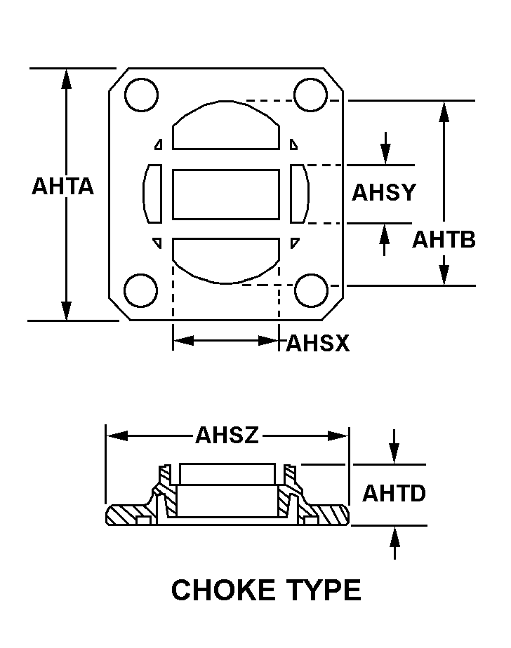
| FLANGE STYLE | C3 CHOKE TYPE FIRST FLANGE C28 COVER TYPE SECOND FLANGE |
| FLANGE INSIDE WIDTH | 0.620 INCHES MINIMUM AND 0.624 INCHES MAXIMUM FIRST FLANGE 0.705 INCHES MINIMUM AND 0.707 INCHES MAXIMUM SECOND FLANGE |
| FLANGE INSIDE HEIGHT | 0.309 INCHES MINIMUM AND 0.313 INCHES MAXIMUM FIRST FLANGE 0.394 INCHES MINIMUM AND 0.396 INCHES MAXIMUM SECOND FLANGE |
| FLANGE OUTSIDE WIDTH | 1.297 INCHES MINIMUM AND 1.327 INCHES MAXIMUM FIRST FLANGE 1.297 INCHES MINIMUM AND 1.327 INCHES MAXIMUM SECOND FLANGE |
| FLANGE OUTSIDE HEIGHT | 1.297 INCHES MINIMUM AND 1.327 INCHES MAXIMUM FIRST FLANGE 1.297 INCHES MINIMUM AND 1.327 INCHES MAXIMUM SECOND FLANGE |
| FLANGE INSIDE DIAMETER | 0.360 INCHES MINIMUM FIRST FLANGE 0.390 INCHES MAXIMUM SECOND FLANGE 0.298 INCHES MINIMUM THIRD FLANGE 0.328 INCHES MAXIMUM FOURTH FLANGE |
| FLANGE DEPTH | 0.360 INCHES MINIMUM AND 0.375 INCHES MAXIMUM FIRST FLANGE 0.298 INCHES MINIMUM AND 0.328 INCHES MAXIMUM SECOND FLANGE |
| VOLTAGE STANDING WAVE RATIO | 1.10 |
| (NON-CORE DATA) FLANGE MANUFACTURER PART NUMBER | M3922/59-1 FIRST FLANGE M3922/53-5 SECOND FLANGE |
| III FSC APPLICATION DATA | ANTENNA-RECEIVER TRANSMITTER GROUP,MISSILE TRACKING |
| MANUFACTURERS CODE | 18876 |
| DESIGN CONTROL REFERENCE | 9151044 |
Restrictions/Controls & Freight Information | NSN 1430-00-593-7840
| Category | Code | Description |
|---|---|---|
| Hazardous Material Indicator Code | N | There is no data in the HMIS and the NSN is in an FSC not generally suspected of containing hazardous materials |
| Category | Code | Description |
|---|---|---|
| No Freight Information | ||


