NSN 1285-00-102-4203 001024203
Product Details | WAVEGUIDE ASSEMBLY
1285-00-102-4203 An item consisting of one or more definite lengths of straight or formed, flexible or rigid, prefabricated hollow tubing of conductive material. The tubing has a predetermined cross section and is designed to guide or conduct high frequency electromagnetic energy through its interior. One or more ends are terminated. May include common mounting of a SWITCH, WAVE GUIDE, a DUMMY LOAD, ELECTRICAL and other components such as waveguide section, cable terminal chamber and the like. Excludes COUPLER, ROTARY, RADIO FREQUENCY; COUPLER, DIRECTIONAL; ADAPTER, WAVEGUIDE; and TUNER, WAVEGUIDE.
Part Alternates: 001024203
Fire Control Equipment | Fire Control Radar Equipment, except Airborne
| Supply Group (FSG) | NSN Assign. | NIIN | Item Name Code (INC) |
|---|---|---|---|
| 12 | 00-102-4203 | 00305 ( WAVEGUIDE ASSEMBLY ) |
Request a Quote
What Our Customers Say
Compare
NSNs for Compare ( up to 4 ): Add 1285-00-102-4203
Related Products | NSN 1285-00-102-4203
Technical Data | NSN 1285-00-102-4203
| Characteristic | Specifications |
|---|---|
| STYLE DESIGNATOR | B2 BEND TYPE |
| WAVEGUIDE LONGER OFFSET DISTANCE | 7.120 INCHES NOMINAL |
| WAVEGUIDE OFFSET DISTANCE | 2.500 INCHES NOMINAL |
| CROSS-SECTIONAL SHAPE STYLE | A1 INTERNAL, RECTANGULAR EXTERNAL, RECTANGULAR |
| WAVEGUIDE OUTSIDE WIDTH | 0.997 INCHES MINIMUM AND 1.003 INCHES MAXIMUM |
| WAVEGUIDE INSIDE WIDTH | 0.897 INCHES MINIMUM AND 0.903 INCHES MAXIMUM |
| WAVEGUIDE INSIDE HEIGHT | 0.397 INCHES MINIMUM AND 0.403 INCHES MAXIMUM |
| WAVEGUIDE OUTSIDE HEIGHT | 0.497 INCHES MINIMUM AND 0.503 INCHES MAXIMUM |
| FLEXIBILITY | FLEXIBLE SINGLE TUBING SEGMENT |
| TUBING WALL CONSTRUCTION STYLE | J9 CORRUGATED SINGLE TUBING SEGMENT |
| MATERIAL | STEEL CORROSION RESISTING SINGLE TUBING SEGMENT RUBBER SYNTHETIC SINGLE TUBING JACKET |
| SURFACE TREATMENT | NICKEL SINGLE TUBING SEGMENT INSIDE SURFACES |
| FLANGE QUANTITY | 2 |
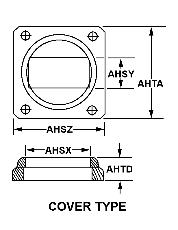
| FLANGE STYLE | C28 COVER TYPE ALL FLANGES |
| FLANGE INSIDE WIDTH | 1.003 INCHES MINIMUM AND 1.006 INCHES MAXIMUM ALL FLANGES |
| FLANGE INSIDE HEIGHT | 0.503 INCHES MINIMUM AND 0.506 INCHES MAXIMUM ALL FLANGES |
| FLANGE OUTSIDE WIDTH | 1.610 INCHES MINIMUM AND 1.640 INCHES MAXIMUM ALL FLANGES |
| FLANGE OUTSIDE HEIGHT | 1.610 INCHES MINIMUM AND 1.640 INCHES MAXIMUM ALL FLANGES |
| FLANGE DEPTH | 0.422 INCHES MINIMUM AND 0.453 INCHES MAXIMUM ALL FLANGES |
| FLANGE CONNECTING FACILITY AND QUANTITY | 4 UNTHREADED HOLE ALL FLANGES SINGLE CONNECTION FACILITY |
| FLANGE CONNECTING HOLE DIAMETER | 0.169 INCHES MINIMUM AND 1.172 INCHES MAXIMUM ALL FLANGES SINGLE CONNECTION FACILITY |
| MAXIMUM OPERATING PRESSURE | 5.0 POUNDS PER SQUARE INCH GAGE |
| VOLTAGE STANDING WAVE RATIO | 1.06 |
| (NON-CORE DATA) FLANGE MANUFACTURER PART NUMBER | M3922/53-1 ALL FLANGES |
| MANUFACTURERS CODE | 52564 |
| DESIGN CONTROL REFERENCE | C1-46540 |
Restrictions/Controls & Freight Information | NSN 1285-00-102-4203
| Category | Code | Description |
|---|---|---|
| Hazardous Material Indicator Code | N | There is no data in the HMIS and the NSN is in an FSC not generally suspected of containing hazardous materials |
| Category | Code | Description |
|---|---|---|
| No Freight Information | ||


